
Choosing the right Bevel Gears begins with understanding how each design behaves under real operating conditions. A gearbox on a conveyor may need different teeth than a compact automotive differential. Load direction, speed, noise, space, lubrication, and production cost all influence the final choice.
Hermann J. Stadtfeld, a recognized bevel gear specialist and author, explains, “Every bevel gear design is a compromise among geometry, strength, noise, and manufacturability.” That principle remains practical for buyers comparing suppliers and specifications. A polished catalogue can look convincing. However, tooth accuracy, heat treatment, backlash, surface finish, and inspection records reveal far more.
This guide examines the top 10 types of Bevel Gears used across industrial machinery, vehicles, robotics, agricultural equipment, and power transmission systems. It considers straight bevel, spiral bevel, zerol bevel, hypoid, miter, crown, angular, face, skew, and spiroid designs. Each type offers a different balance between torque capacity, operating noise, efficiency, installation flexibility, and maintenance demands.
Some choices are not obvious.
A spiral bevel gear may reduce noise, yet it can require more careful adjustment and lubrication. A miter gear can transmit motion at a right angle, but it provides no speed reduction by itself. Hypoid gears offer excellent packaging advantages, although sliding action may increase heat and lubricant requirements.
Buyers should not rely on tooth shape alone. Supplier experience, material certificates, dimensional reports, and application testing matter equally. Even this list has limitations. Actual performance depends on the complete gear set, housing stiffness, alignment, duty cycle, and maintenance quality.
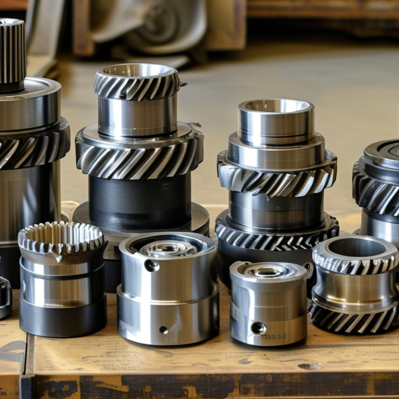
Bevel gears transfer motion between intersecting or offset shafts, usually changing direction by 90 degrees. Their conical tooth surfaces make them different from ordinary spur gears.
Buyers often compare ten common types: straight, spiral, Zerol, hypoid, miter, crown, face, skew, beveloid, and spiroid gears. This list is useful, but classifications can overlap.
The main criteria are tooth shape, shaft arrangement, offset, contact pattern, speed, and load. Straight bevel gears use direct teeth and suit moderate speeds. Spiral bevel gears engage gradually, reducing noise and vibration. Zerol gears offer curved teeth with limited spiral action.
Hypoid gears handle offset shafts and high torque, but sliding creates heat. Miter gears keep a one-to-one ratio, often at a 90-degree angle. Crown, face, skew, beveloid, and spiroid designs serve more specialized layouts.
Tooth accuracy, material, lubrication, backlash, and mounting space also affect selection. A smaller gear is not automatically better.
Tips: Confirm shaft angles and rotation direction from the drawing, not memory. Check the required ratio, input speed, torque, duty cycle, and operating temperature. Ask for contact-pattern inspection data when precision matters. In practical installations, alignment errors can dominate performance. I have seen a theoretically suitable gear fail early because the housing flexed. That detail is easy to miss. Also, noise targets may conflict with cost, size, and serviceability. A careful buyer should compare the complete transmission, not only the gear label.
What Are the Top 10 Types of Bevel Gears for Buyers?
Straight and spiral bevel gears remain practical choices for standard power transmission. Straight bevel gears use straight teeth and offer simple, economical construction. They suit moderate speeds, right-angle drives, and accessible maintenance. However, tooth engagement can create noticeable noise and vibration at higher speeds.
Spiral bevel gears use curved teeth for smoother contact and greater load capacity. Their quieter operation fits conveyors, machine tools, pumps, and industrial reducers. The U.S. Department of Energy reports that motor-driven systems can account for about 70% of industrial electricity use, making transmission efficiency a serious purchasing factor. Gear losses still matter. Small losses become expensive during continuous operation.
The wider bevel-gear family includes zerol, hypoid, miter, crown, angular, offset, and duplex types. Buyers should check torque, speed, ratio, shaft angle, lubrication, backlash, and operating temperature. AGMA standards provide useful guidance for rating gear capacity and manufacturing quality. In field inspections, tooth contact patterns often reveal more than a catalogue rating. I would not select spiral gears automatically. Their performance can justify higher cost, but installation accuracy and lubrication become less forgiving. A 2023 industrial gear market assessment by Grand View Research projected continued market growth through 2030, reflecting expanding demand for reliable power transmission. Yet market growth does not replace engineering judgment. Examine the actual duty cycle. Also verify noise limits and service access.
What Are the Top 10 Types of Bevel Gears for Buyers?
Zerol, hypoid, and curved-tooth bevel gears deserve close attention during gear selection. Each design changes noise, torque capacity, efficiency, and maintenance needs. Zerol gears use curved teeth with nearly zero spiral angle. They offer smoother engagement than straight bevel gears. Their tooth contact remains relatively compact. This can support quiet operation in limited spaces. However, their advantages depend heavily on accurate alignment and proper tooth finishing.
Hypoid bevel gears place the shafts at an offset. This layout can lower the driven shaft and improve equipment packaging. Their larger contact area supports high torque transmission. Yet, sliding action creates more heat and friction. Buyers should confirm lubricant specifications, cooling conditions, and expected service intervals. A small error here can shorten gear life quickly. Curved-tooth bevel gears provide gradual tooth engagement and reduced impact loading. They suit applications where vibration control matters. Industrial drives, vehicle axles, and compact motion systems often use them.
The remaining bevel gear types may include straight, spiral, crown, miter, and custom forms. Selection should begin with speed, ratio, transmitted torque, and shaft angle. Check backlash, hardness, tooth accuracy, housing stiffness, and inspection records. In practice, the “best” gear is rarely the most powerful one. It is the design that matches the entire operating environment. A quieter gear may lose efficiency. A stronger gear may require costlier lubrication. Buyers should compare measured data, not attractive catalog claims. Mistakes happen. Good engineering leaves room to question the first choice.
| Rank | Bevel Gear Type | Tooth Design and Geometry | Typical Shaft Arrangement | Main Advantages | Key Limitations | Common Applications | Buyer Selection Notes |
|---|---|---|---|---|---|---|---|
| 1 | Spiral Bevel Gear | Curved teeth with a spiral angle; tooth engagement is gradual rather than instantaneous. | Usually intersecting shafts, commonly at 90°. | High load capacity, smoother operation, lower impact noise, and better suitability for continuous service than straight-tooth designs. | More expensive to manufacture; produces axial and radial thrust that must be supported by suitable bearings. | Automotive differentials, industrial gearboxes, machine tools, conveyors, and power transmission systems. | Choose when quiet running, higher speed, and sustained torque capacity are more important than the lowest purchase price. |
| 2 | Straight Bevel Gear | Straight radial teeth that converge toward the gear apex. | Intersecting shafts, often at 90°. | Simple geometry, relatively low manufacturing cost, easy inspection, and efficient right-angle power transfer at moderate speeds. | Higher noise and vibration at elevated speed; tooth impact limits smoothness and high-speed performance. | Hand tools, low-speed machinery, agricultural equipment, and basic right-angle drives. | Suitable for moderate speed and intermittent service where simplicity and cost control are priorities. |
| 3 | Zerol Bevel Gear | Curved teeth with a nominally zero spiral angle at the midpoint of the tooth face; it combines features of straight and spiral bevel gears. | Intersecting shafts, commonly at 90°. | Smoother and quieter than straight bevel gears while retaining relatively manageable thrust compared with strongly spiral designs. | More specialized manufacturing and setup; it may not match a spiral bevel gear's capacity in every high-speed application. | Compact gear drives, industrial machinery, vehicle systems, and applications requiring balanced noise and thrust characteristics. | Consider when a buyer needs smoother operation than straight teeth provide but wants a relatively moderate spiral effect. |
| 4 | Hypoid Gear | Spiral-like curved teeth with non-intersecting, offset shaft axes; the pinion is positioned above or below the gear centerline. | Non-intersecting shafts, typically arranged at approximately 90°. | High torque capacity, quiet operation, compact packaging, and increased contact ratio from tooth sliding. | Greater sliding friction, lower efficiency than many conventional bevel arrangements, and a requirement for suitable extreme-pressure lubricant. | Automotive final drives, rear axles, compact right-angle reducers, and heavy-duty drivetrain systems. | Verify lubricant compatibility, thermal conditions, offset direction, efficiency requirements, and allowable backlash before purchase. |
| 5 | Curved-Tooth Bevel Gear | Teeth follow a curved path across the face width; the term is often used broadly for spiral or other non-straight bevel tooth forms. | Most commonly intersecting shafts, although the exact arrangement depends on the design. | Improved tooth contact, smoother engagement, reduced impact loading, and lower operating noise than straight-tooth gears. | Performance varies significantly with curvature, spiral angle, tooth form, and manufacturing accuracy; terminology can be inconsistent between suppliers. | Industrial reducers, automotive systems, robotics, aerospace mechanisms, and high-quality motion drives. | Request the exact tooth standard, spiral angle, pressure angle, contact ratio, and load rating rather than relying only on the general term. |
| 6 | Miter Gear | A matched pair of bevel gears with equal tooth counts and a 1:1 speed ratio. | Intersecting shafts, commonly at 90°; other shaft angles are possible with matched geometry. | Changes the direction of rotation without changing speed or torque ratio; compact and useful for synchronized shaft layouts. | It does not provide speed reduction or multiplication; load capacity and efficiency depend on the tooth form and alignment. | Right-angle drives, indexing mechanisms, packaging equipment, hand-operated mechanisms, and synchronized machine shafts. | Confirm that a 1:1 ratio is required and specify whether straight, spiral, or another tooth form is preferred. |
| 7 | Crown Bevel Gear | Bevel gear with teeth projecting approximately perpendicular to the gear axis, giving the gear a crown-like profile. | Usually intersecting shafts, often near 90°. | Can transmit motion between perpendicular shafts and may offer useful layout flexibility in low-speed mechanisms. | Generally unsuitable for high-speed or high-load service; tooth contact and alignment must be carefully controlled. | Clocks, instruments, educational mechanisms, light-duty motion systems, and specialized low-speed devices. | Use for light loads and moderate speeds unless a detailed engineering analysis confirms suitability for heavier duty. |
| 8 | Angular Bevel Gear | Bevel gear set designed for a shaft intersection angle other than the common 90° arrangement. | Intersecting shafts at a specified included angle, such as 45°, 60°, or another design value. | Enables flexible machine layouts and can direct power around obstructions or through non-standard transmission paths. | Requires matched geometry and precise specification of the shaft angle; replacement interchangeability is limited. | Special-purpose machinery, aerospace mechanisms, packaging systems, and equipment with angled shaft layouts. | Provide the exact shaft angle, pitch cone data, tooth system, mounting distance, and rotation direction when requesting quotations. |
| 9 | Skew Bevel Gear | Bevel-type gear arrangement used for non-intersecting and non-parallel shaft axes; tooth geometry is designed for skewed transmission. | Non-intersecting, non-parallel shafts. | Offers packaging flexibility where conventional intersecting bevel gears cannot fit. | More complex contact conditions, significant sliding may occur, and efficiency, noise, and wear are highly dependent on design accuracy and lubrication. | Specialized reducers, compact mechanisms, instrumentation, and custom motion-transmission systems. | Obtain verified contact analysis, efficiency data, lubrication requirements, and allowable misalignment limits for the intended duty cycle. |
| 10 | Beveloid Gear | Conical gear with an involute tooth form modified to support controlled changes in tooth thickness or operating geometry across the face width. | Can be configured for intersecting or specially arranged shafts, depending on the design. | Can accommodate certain center-distance, backlash, and assembly-tolerance requirements while supporting compact gear layouts. | Design and inspection are more specialized; operating performance depends strongly on the specified geometry and manufacturing accuracy. | Robotics, compact gearboxes, automotive mechanisms, precision equipment, and applications with demanding packaging constraints. | Ask for detailed geometry, contact pattern, backlash range, heat-treatment condition, and dimensional inspection data. |
Choosing among the top 10 bevel gear types requires more than comparing tooth shapes. Straight bevel gears suit low-speed, right-angle drives with moderate loads. Spiral bevel gears handle higher speeds and reduce impact noise. Zerol bevel gears offer a middle path, using curved teeth with limited axial thrust.
Miter gears typically use a 1:1 ratio for compact direction changes. Crown gears can mesh with spur gears, making them useful when shafts intersect without strict alignment. Face gears support unusual layouts, but their load capacity demands careful testing. Hypoid gears provide high torque and quiet operation, although their sliding contact increases heat and lubrication needs. Beveloid gears help correct shaft-offset or mounting challenges. Skew bevel designs remain specialized and require precise engineering.
Check the data. Grand View Research estimated the global gear market at about USD 73 billion in 2023, with continued growth expected through 2030. That expansion reflects demand from vehicles, automation, energy equipment, and industrial machinery. ISO 23509 also emphasizes accurate bevel-gear geometry, including pitch angles, tooth proportions, and contact patterns. Buyers should request these measurements, not only a catalog rating. A neat catalog can mislead. Verify torque, speed, backlash, material, heat treatment, and service factor. Miter gears look simple. Alignment errors are not. Spiral designs may reduce noise, yet they can raise manufacturing and maintenance costs. The best selection depends on the actual duty cycle, installation space, lubrication method, and acceptable risk.
Buyers comparing the top ten bevel gear types should begin with the working conditions. Straight bevel gears suit moderate loads and simple layouts. Spiral bevel gears run more quietly under higher loads. Zerol gears offer smoother contact without strong axial thrust. Hypoid gears handle offset shafts and high reduction ratios. Miter gears change direction without changing speed. Crown gears tolerate some alignment variation. Angular bevel gears fit unusual shaft arrangements. Beveloid gears help correct mounting or tooth-contact problems. Skew bevel gears support compact, specialized drives. Spiroid gears serve applications needing high reduction in limited space.
Load, speed, space, and cost often conflict. A conveyor carrying heavy boxes may need spiral bevel gears with hardened teeth. A small actuator may prioritize a compact miter gear instead. Space changes everything. Check shaft angle, housing clearance, lubrication access, and mounting direction before selecting a gear.
Speed also affects noise, heat, and service life. High-speed systems need accurate tooth finishing and reliable lubrication. Low-speed equipment may accept a simpler design, but impact loads still matter. Ask for rated torque, allowable speed, efficiency data, backlash, and inspection records. AGMA or ISO-based calculations improve confidence, yet catalog ratings can hide real operating conditions. A spreadsheet may look convincing. Field experience often finds the missing shock load. Cost should include machining, installation, maintenance, and downtime, not only purchase price. Measure twice. A cheaper gear can become expensive when alignment proves difficult.